S35390A实时时钟使用:
1.具体的引脚使用:
SDA
SCL是IIC的两根
XIN,XOUT 是时钟的两根,其中使用的时钟为32.768Khz
INT,INT2,是中断,可以输出单个电平或者时钟。
VDD电源,VSS是地,
2.IIC的频率:0---400Khz
3.设备的控制命令:
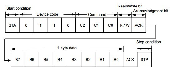
这个命令的意义:
高4位固定:0110,设备号
低4位是命令加读写标识 ,其中bit 0 为1时为读对应的寄存器。
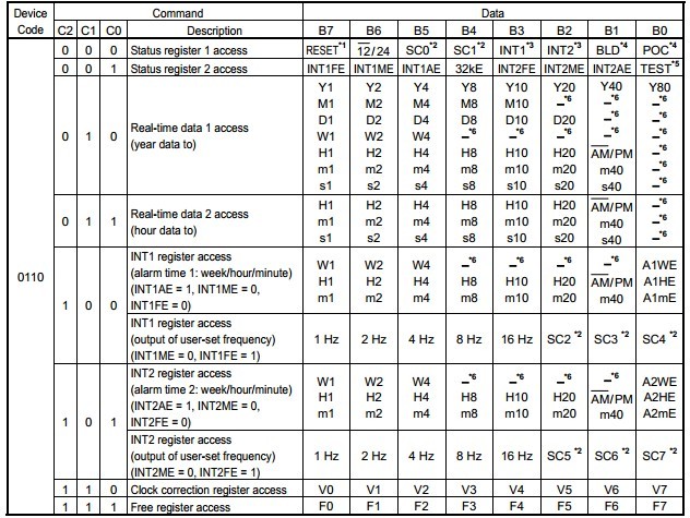
4.表中给出对应寄存器的意义
时间格式为BCD码。
在状态寄存器2中,有控制输出中断的方式,同时通过设置对应的寄存器就可以关断S35390的中断。
5.中断时间的设置。

需要注意的是,bit0 为1时设置时间有效,为0设置时间无效,同样的如果bit0为0,不会产生中断。
6.对于中断的处理,如果清除状态寄存器2,再次打开,在中断时间点不能有效,只能到下次中断才可以。
而对中断的清除是在程序中实现,下面是对具体中断操作的说明。
*1.If users clear INT1AE/INT2AE once; "L" is not output from the 1 INT / 2 INT pin by setting INT1AE/INT2AE enable again,
within a period when the alarm time matches real-time data.
*2. If turning the alarm output on by changing the program, withinthe period when the alarm time matches real-time data,
"L" is output again from the 1 INT / 2 INT pin when the minute is counted up.
7关于时间校正部分:
可以设置每20S校正1次或者每60S校正一次。
在校正之前需要先对该寄存器清零。
具体实现方式:
与S35390A的通信结构体:
typedef struct S35390_info{
unsigned char Func_s35390[2];//send to s35390
unsigned char Recive_data[2];//recive flag from s35390
unsigned char time1[7]; //time1
unsigned char time2[3]; //time2
unsigned char alarm1[4]; //alarm1
unsigned char alarm2[4]; //alarm2
unsigned char correct[2]; //correct
}S35390_info;
S35390A的控制指令:
#define Status1_W 0x60
#define Status1_R 0x61
#define Status2_W 0x62
#define Status2_R 0x63
#define Read_time1_W 0x64 //
#define Read_time1_R 0x65 //
#define Read_time2_W 0x66 //
#define Read_time2_R 0x67 //
#define Int1_W 0x68 //alarm time1:week/hour/minute
#define Int1_R 0x69 //alarm time1:week/hour/minute
#define Int2_W 0x6A //alarm time2:week/hour/minute
#define Int2_R 0x6B //alarm time2:week/hour/minute
#define Clock_correct_W 0x6C
#define Clock_correct_R 0x6D
#define Free_register_W 0x6E
初始化
void init()
{
unsigned char i;
read_IIC(Status1_R,1,Realtimer.Recive_data); //read POC detector power-on
if((Realtimer.Recive_data[0]&0x11)!=0)
{
Realtimer.Recive_data[0]= RESET_S35390A; //24-hour
write_IIC(Status1_W,1,Realtimer.Recive_data); //reset the s35390
read_IIC(Status2_R,1,Realtimer.Func_s35390);
if((Realtimer.Func_s35390[0]&0x01) !=0)
{
Realtimer.Func_s35390[0]= (Realtimer.Func_s35390[0]&0xFE);
write_IIC(Status2_W,1,Realtimer.Func_s35390);
}
Realtimer.Func_s35390[0]= INIT_INTERTUPT; //open the interrupt 0x22
&nbnbsp; write_IIC(Status2_W,1,Realtimer.Func_s35390);
}
IIC的实现方法很多,不做具体介绍
/*
void write_IIC(unsigned int address, unsigned char data_len,unsigned char* buf);//
void read_IIC(unsigned int address, unsigned char data_len,unsigned char* buf);//
*/
具体处理:
void DEAL_func(void)
{
test_connect[0]=SPI_recivebyte();
switch(test_connect[0])
{
case Status1_W: // write
test_connect=0x00;
write_IIC(Status1_W,1,Realtimer.Func_s35390); //reset the s35390
break;
case Status1_R: //read
read_IIC(Status1_R,1,Realtimer.Func_s35390); //reset the s35390
test_connect=0x00;
break;
*/
case Status2_W:
test_connect[0]=0x00;
write_IIC(Status2_W,1,Realtimer.Func_s35390);
break;
case Status2_R:
read_IIC(Status2_R,1,Realtimer.Func_s35390);
test_connect[0]=0x00;
&nbnbsp; break;
case Read_time1_W:
test_connect[0]=0x00;
write_IIC(Read_time1_W,7,Realtimer.time1);
break;
case Read_time1_R:
test_connect[0]=0x00;
read_IIC(Read_time1_R,7,Realtimer.time1);
break;
case Read_time2_W:
test_connect[0]=0x00;
write_IIC(Read_time2_W,3,Realtimer.time2);
&nbnbsp; break;
case Read_time2_R:
test_connect[0]=0x00;
read_IIC(Read_time2_R,3,Realtimer.time2);
break;
case Int1_W:
nbsp; test_connect[0]=0x00;
write_IIC(Int1_W,4,Realtimer.alarm1);
break;
case Int1_R:
read_IIC(Int1_R,4,Realtimer.alarm1);
&nbnbsp; test_connect[0]=0x00;
Break;
case Int2_W:
test_connect[0]=0x00;
write_IIC(Int2_W,4,Realtimer.alarm2);
break;
case Int2_R:
// read_IIC(Int2_R,4,Realtimer.alarm2);
test_connect[0]=0x00;
break;
case Clock_correct_W:
test_connect[0]=0x00;
nbsp; write_IIC(Clock_correct_W,1,Realtimer.correct);
break;
case Clock_correct_R:
read_IIC(Clock_correct_R,1,Realtimer.correct);
test_connect[0]=0x00;
break;
default: break;
}
}


